
Skip to content
CompFlow mark CompFlow
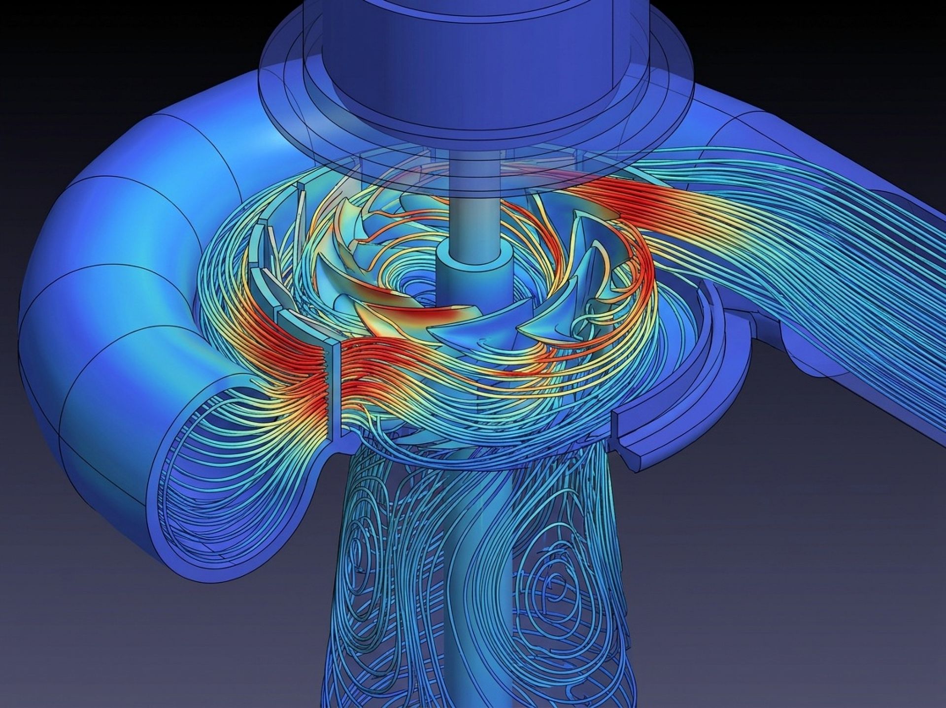
CFD simulation of a turbomachinery volute and impeller showing velocity streamlines through the blade passages
SECTORS / 08 — ENERGY

From wind farm yield to turbomachinery stage detail.

From wind farms to high-fidelity turbomachinery simulations across the energy sector. Yield predictions and efficiency guarantees both rest on flow physics that is expensive to measure and cheap to get wrong.

BRIEF Read the ENERGY sector brief
01 — SECTOR NEEDS

What this sector needs from CFD

Revenue and warranty exposure follow directly from predicted performance, so the sector needs simulation resolving atmospheric inflow, wake losses and stage-level machine behaviour with quantified uncertainty.

Atmospheric inflow realism Terrain, roughness, stability and shear reproduced so hub-height wind resource is representative of the site rather than idealised.
Wake and array losses Turbine-to-turbine wake interaction, deep-array effects and blockage, including neighbouring farm influence on yield.
Turbomachinery stage accuracy Blade-row interaction, tip leakage, secondary flows and off-design behaviour resolved for compressors, turbines and pumps.
Thermal and combustion coupling Heat transfer, cooling flows and combustion behaviour where efficiency limits are set by material temperature.
Uncertainty quantification Sensitivity of predictions to inflow, model and geometry assumptions — essential when figures back financial guarantees.
02 — REPRESENTATIVE CASES

Typical studies we run

06 CASE TYPES
01

Wind resource over complex terrain

Microscale flow modelling over hills, forests and escarpments to correct mast measurements to turbine positions.

Hub-height speed Shear / turbulence Speed-up factors
02

Wake losses and layout optimisation

Array wake interaction across the wind rose to quantify losses and improve turbine positioning and yaw strategy.

Array efficiency Wake deficit AEP delta
03

Rotor blade aerodynamics

Blade sectional and full-rotor performance including stall, soiling sensitivity and add-on device gains.

Power curve Thrust Loads
04

Compressor and turbine stages

Multi-stage machine performance, surge margin and secondary loss breakdown at design and part-load operation.

Efficiency maps Surge margin Loss audit
05

Hydro and pump systems

Draft tubes, intakes, volutes and pump-turbine passages, including cavitation onset and swirl-induced losses.

Head loss NPSH margin Cavitation extent
06

Combustion and thermal plant flows

Burner mixing, boiler and heat-exchanger flow distribution, emissions trends and cooling-tower plume behaviour.

Temperature fields Emission trends
03 — POLICY & COMPLIANCE

Requirements verifiable through CFD

Simulation supports — and in several frameworks explicitly permits — demonstration of compliance. We agree the acceptance criteria and validation evidence with you and the approving body before the study begins.

IEC 61400-1
Wind turbine design requirements
Site-suitability assessment needs turbulence intensity, shear and inflow-angle values at each position — quantities routinely produced by CFD for complex terrain.
IEC 61400-12-1 / -12-4
Power performance measurement
Site calibration and numerical flow-correction of power curves are explicitly supported by flow modelling of the terrain.
ASME PTC 10 / PTC 46
Compressor and plant performance tests
Guarantee testing and correction to reference conditions are supported by machine simulation of the tested operating points.
ISO 5801
Industrial fan performance testing
Installation effects and inlet distortion that penalise measured performance can be diagnosed and corrected before testing.
IED 2010/75/EU
Industrial emissions
Combustion and stack dispersion modelling supports permit applications and demonstration of emission and air-quality limits.

Yield or efficiency figure you need to defend?

Discuss your case See our services