
Skip to content
CompFlow mark CompFlow
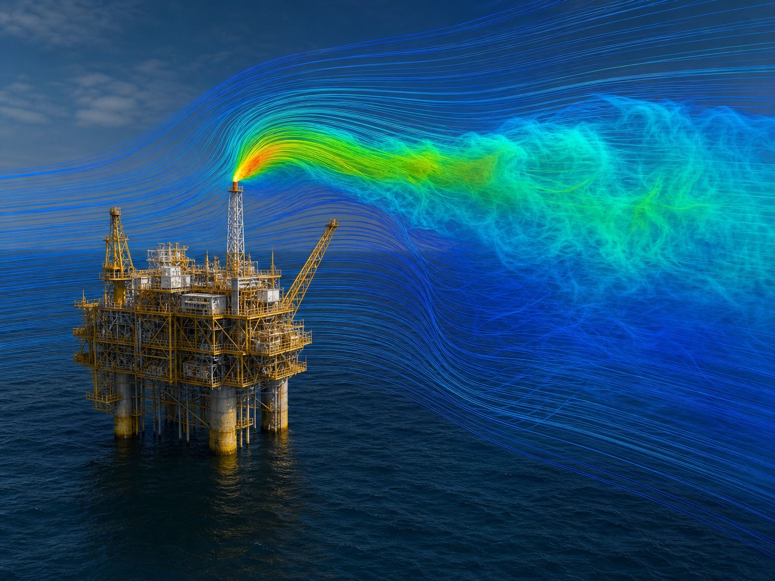
CFD gas dispersion simulation over an offshore oil and gas platform showing flare plume streamlines
SECTORS / 03 — OIL & GAS

Dispersion, flow assurance and safety on live assets.

One of our primary fields, backed by a verified methodology covering gas dispersion, flow assurance and process safety. Studies here feed directly into risk assessments and permit documentation, so traceability matters as much as accuracy.

BRIEF Read the OIL & GAS sector brief
01 — SECTOR NEEDS

What this sector needs from CFD

Consequence modelling drives layout, detector placement and manning decisions, so the sector needs simulation that handles congested geometry, buoyant and dense gases, and multiphase pipeline behaviour under credible worst-case scenarios.

Congested-geometry dispersion Releases inside process modules where integral models fail — CFD resolves the effect of decks, walls and equipment on cloud build-up and ventilation.
Dense and buoyant gas behaviour Correct treatment of heavier-than-air and light gases, jet momentum, entrainment and stratification in confined spaces.
Multiphase flow assurance Slugging, hold-up, erosion risk and separator performance across the operating envelope, including turndown and start-up.
Ignition and blast context Flammable cloud volume and location as input to explosion overpressure assessment and structural response.
Auditable methodology Documented mesh, model and validation choices that survive third-party review by verifiers and regulators.
02 — REPRESENTATIVE CASES

Typical studies we run

06 CASE TYPES
01

Flammable gas dispersion

Release scenarios across wind directions and rates, quantifying flammable cloud volume and residence time within congested modules.

Cloud volume LFL contours Detector coverage
02

Toxic release and H₂S exposure

Exposure mapping for toxic components at manned locations, control rooms and escape routes under adverse weather.

Concentration maps Exposure duration
03

Module ventilation adequacy

Natural and forced ventilation rates in enclosed and semi-enclosed areas, supporting hazardous-area classification and dilution claims.

Air changes/hour Dilution factor
04

Flare radiation and dispersion

Thermal radiation footprint and unburnt gas dispersion from flare and cold-vent systems, including wind-blown flame effects.

Radiation contours Exclusion zones
05

Separator and vessel internals

Internal flow distribution, residence time and carry-over prediction for separators, scrubbers and slug catchers.

Separation efficiency Carry-over
06

Erosion and sand transport

Particle-laden flow through bends, chokes and tees to locate erosion hotspots and set inspection priorities.

Erosion rate Impact locations
03 — POLICY & COMPLIANCE

Requirements verifiable through CFD

Simulation supports — and in several frameworks explicitly permits — demonstration of compliance. We agree the acceptance criteria and validation evidence with you and the approving body before the study begins.

NORSOK Z-013
Risk and emergency preparedness analysis
Explicitly recognises CFD for dispersion and explosion consequence modelling; our documentation follows the expected structure for scenario definition and reporting.
IEC 60079-10-1
Hazardous area classification
Zone extent and ventilation-availability assessment can be substantiated with CFD dilution and dispersion results rather than generic tables alone.
API 521 / ISO 23251
Pressure relieving and depressuring
Flare and vent dispersion plus radiation levels are verified against the standard’s exposure criteria for personnel and equipment.
ISO 13702
Control and mitigation of fires and explosions
Layout, segregation and ventilation measures on offshore installations are demonstrated using consequence modelling.
Seveso III (2012/18/EU)
Major accident hazards
Safety reports for upper-tier establishments require credible consequence assessment — CFD supplies the dispersion and radiation evidence.

Need dispersion or flow assurance evidence for a safety case?

Discuss your case See our services